- 您现在的位置:买卖IC网 > Sheet目录17344 > IRDC3065 (International Rectifier)LOW PWR SWTCH REG REF DESIGN KIT
�� �
�
�IRU3065(PbF)�
�THEORETICAL� OPERATION�
�Operation-Regulation� Mode�
�V� g� a� te�
�reference� of� the� chip,� which� is� set� to� be� 150mV� (for�
�Vcc=5V),� the� flip-flop� is� reset� and� the� PMOS� is� turned�
�off.� The� inductor� current� is� discharged� through� diode�
�D2� to� the� load.� The� load� voltage� increases.� When� the�
�inductor� current� decreases� to� zero,� the� output� current�
�is� supplied� by� the� output� capacitor� and� the� output� volt-�
�age� decreases� until� next� cycle� starts.� In� this� mode,� the�
�voltage� at� V� SEN� pin� is� controlled� near� zero.� Therefore,�
�the� output� voltage� is� regulated� at:�
�V� in�
�-V� OUT� =�
�R3�
�R2�
�� V� REF�
�V� o� lta� g� e� a� cro� ss�
�th� e� in� d� u� cto� r�
�V� out� ?� V� D�
�In� the� evaluation� board,� the� output� voltage� is� regulated�
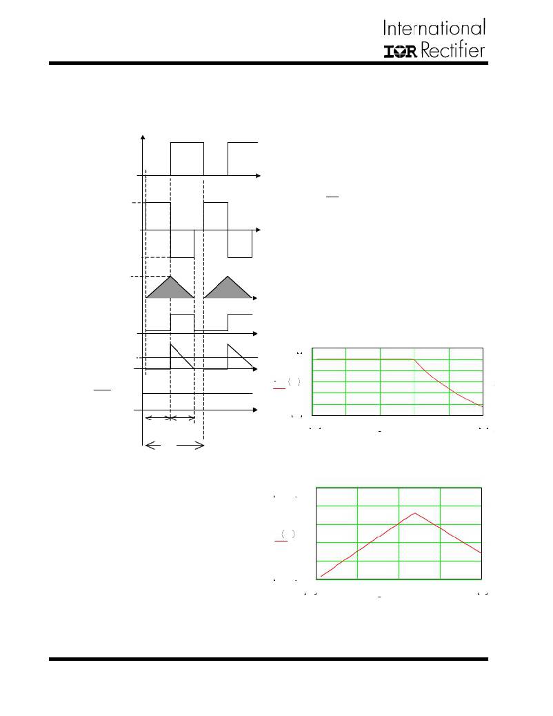
�at� -5V,� as� shown� in� figure� 7.� The� steady� state� of� the�
�converter� should� be� operated� in� this� mode.� One� feature�
�in� this� mode� is� that� the� shaded� inductor� current� in� fig-�
�ure� 18� stays� unchanged.� The� average� output� diode� cur-�
�In� d� u� cto� r�
�cu� rre� n� t�
�I� peak�
�rent� equals� output� current.� When� the� switching� period�
�decreases� and� frequency� goes� up,� the� average� diode�
�current� increases� to� support� more� output� current.� The�
�O� u� tp� u� t� o� f� cu� rre� n� t�
�co� m� p� a� ra� to� r�
�switching� frequency� increases� linearly� when� the� load�
�current� increases� as� shown� in� figure� 20.�
�O� u� tp� u� t� d� io� d� e�
�cu� rre� n� t�
�I� out�
�5�
�6�
�5�
�4�
�?� V� out�
�=�
�R 3�
�R� 2�
�?� V� ref�
�V� out� I� out�
�3�
�2�
�1�
�0.75�
�0�
�0�
�0.16�
�0.32�
�0.48�
�0.64�
�0.8�
�t� on�
�t� 1�
�0.02�
�I� out�
�0.8�
�T� s�
�Figure� 19� -� Theoretical� output� voltage� (-V� OUT� )�
�versus� output� current� for� IRU3065� controlled� buck�
�boost� evaluation� board.(assume� VIsen=0.2V)�
�Figure� 18� -� Operation� waveforms� of� IRU3065� con-�
�1.083� .� 10�
�1.5� .� 10�
�6�
�6�
�trolled� buck� boost� converter� at� regulation� mode.�
�1.2� .� 10�
�6�
�In� general,� IRU3065� controlled� buck� boost� converter�
�9� .� 10�
�5�
�is� operated� in� two� modes� depending� on� the� load� cur-�
�rent.� When� the� load� current� is� small,� the� buck� boost�
�f� s� I� out�
�6� .� 10�
�5�
�3� .� 10�
�4.583� .� 10�
�I� out�
�operated� in� first� mode� (regulation� mode).� The� operation�
�waveforms� are� shown� in� figure� 18.� In� this� mode,� the�
�inductor� current� in� the� buck� converter� is� discontinuous.�
�Basic� Operation�
�When� the� voltage� at� V� SEN� pin� is� below� zero,� the� flip-flop�
�inside� the� IC� is� set� and� the� V� GATE� pin� output� low,� which�
�trigger� the� PMOS� in� the� power� stage,� the� output� induc-�
�tor� current� increases� from� zero.� When� sensed� inductor�
�current� voltage� at� I� SEN� pin� reaches� the� internal� current�
�5�
�4�
�0�
�0� 0.2� 0.4� 0.6�
�0.02�
�Figure� 20� -� Theoretical� switching� frequency� versus�
�output� current� for� evaluation� board.(assume�
�VIsen=0.2V)�
�0.8�
�0.8�
�10�
�www.irf.com�
�发布紧急采购,3分钟左右您将得到回复。
相关PDF资料
R1D-0509/H-R
CONV DC/DC 1W 05VIN +/-09VOUT
AS4PG-M3/87A
DIODE STD 4A 400V SMPC
RS3-4815D/H2
CONV DC/DC 3W 36-72VIN +/-15VOUT
MAX6162BESA+
IC VREF SERIES PREC 2.048V 8SOIC
GBM30DCTH-S288
CONN EDGECARD 60POS .156 EXTEND
ECM08DRSH-S288
CONN EDGECARD 16POS .156 EXTEND
GEM12DTKI
CONN EDGECARD 24POS DIP .156 SLD
ECM08DRSD-S288
CONN EDGECARD 16POS .156 EXTEND
相关代理商/技术参数
IRDC3073
功能描述:PWM CONTROLLER DESIGN KIT RoHS:否 类别:编程器,开发系统 >> 过时/停产零件编号 系列:- 标准包装:1 系列:- 类型:MCU 适用于相关产品:Freescale MC68HC908LJ/LK(80-QFP ZIF 插口) 所含物品:面板、缆线、软件、数据表和用户手册 其它名称:520-1035
IRDC3137
功能描述:KIT REFERENCE DESIGN W/IRU3137 RoHS:否 类别:编程器,开发系统 >> 过时/停产零件编号 系列:- 标准包装:1 系列:- 类型:MCU 适用于相关产品:Freescale MC68HC908LJ/LK(80-QFP ZIF 插口) 所含物品:面板、缆线、软件、数据表和用户手册 其它名称:520-1035
IRDC3138
制造商:Vishay Intertechnologies 功能描述:IRU3138, SYNCHRONOUS BUCK REGULATOR, EVAL BOARD, Silicon Manufacturer:Vishay, Si
IRDC3138EVAL
制造商:IRF 制造商全称:International Rectifier 功能描述:EVALUATION BOARD USER GUIDE
IRDC3146
功能描述:KIT REFERENCE DESIGN W/IRU3146 RoHS:否 类别:编程器,开发系统 >> 过时/停产零件编号 系列:- 标准包装:1 系列:- 类型:MCU 适用于相关产品:Freescale MC68HC908LJ/LK(80-QFP ZIF 插口) 所含物品:面板、缆线、软件、数据表和用户手册 其它名称:520-1035
IRDC3146EVAL
制造商:IRF 制造商全称:International Rectifier 功能描述:IRU3146 EVALUATION BOARD USER GUIDE
IRDC3473
功能描述:电源管理IC开发工具 9999V 999A POL IC RoHS:否 制造商:Maxim Integrated 产品:Evaluation Kits 类型:Battery Management 工具用于评估:MAX17710GB 输入电压: 输出电压:1.8 V
IRDC3475
功能描述:电源管理IC开发工具 9999V 999A POL IC RoHS:否 制造商:Maxim Integrated 产品:Evaluation Kits 类型:Battery Management 工具用于评估:MAX17710GB 输入电压: 输出电压:1.8 V